Description
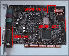
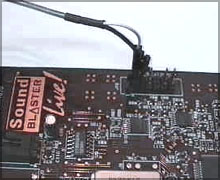
SPDIF connectors on Soundblaster Live
© people.freenet.de/apslive/digital.html
Even the SBLive Value has a nice set of (SPDIF) Digital Input Output Interfaces. There are two different pin layouts - one using a 12 pin and one using a 40 pin connector ! Make sure you choose the right pin layout (See bottom of this page)
| Digital I/O using the SBLive APS | ||
| SBLive Value Location | ||
| Digital Inputs: | 48 kHz or 44.1 kHz | |
| Spdif in 1 | CD (SPDIF) input connector | |
| Spdif in 2 | SPDIF EXT connector pin 1 | |
| Digital Outputs: | 48kHz | |
| Digital Out 1 | Pin 1 on SPDIF EXT connector | |
| Digital Out 2 | Pin 9 on SPDIF EXT connector | |
| SBLive Full Location | ||
| Digital Inputs: | 48 kHz or 44.1 kHz | |
| Spdif in 1 | CD (SPDIF) input connector | |
| Spdif in 2 | I/O card RCA input or pin 15 | |
| Digital Outputs: | 48kHz | |
| Digital Out 1 | (SPDIF) out 0 = pin 17 on I/O card | |
| Digital Out 2 | (SPDIF) out 1 = pin 19 on I/O cable | |
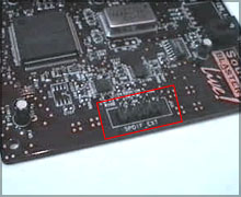
Live Value (full and detail view)
 |
 |
One user in the SBLive Music Newsgroup did find an Article in the Sound-on-Sound magazine which is quite interesting - it describes how to do Digital Copies using the APS bypassing the internal resampling of the Emu10k1:
"One final point for APS owners is that there is apparently a way to achieve bit-for-bit copies. It only works with the ASIO driver and 48kHz signals. First you need to set your DAT recorder (or other digital device) to slave to the fixed 48kHz clock signal from the APS digital output. Then you record using either of the two S/PDIF inputs of the card, but switch off the Econtrol mixer. This should ensure that no sample-rate conversion takes place, and that the file recorded to your hard drive is identical to the original."
Select ASIO rec and NONE as source on the EMU mixer - Enable Inputs 3-4 on Cubase - monitor if you need and Record. You'll notice that rec. gain controls and EMU10K1 DSP are excluded from the path of spdif incoming signal.
| Connecting SPDIF |
| Remember: Digital SPDIF connections are done by connecting Input-Output and GND-GND |
Connecting a SBLive "Value" with an APSLive "Value" (12 pin connector)
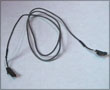 |
You can use the digital audio CD cable included. Or use a standard CD Audio -> Soundcard connector cable and tear apart some plastic so that it fits our needs. |
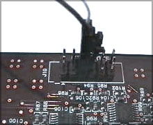 |
Connect pins 5 and 6 on the SB card to pins 1 and 2 on the APS-card. Pin 5 - Pin 2 (Ground - Ground) Pin 6 - Pin 1 (Input - Output) |
 |
| SPDIF on SB Live! | |
| 12 pin connector layout | 40 pin connector layout |
| 01 - SPDIF00 | 01 - VCC (+5V power supply) |
| 02 - Ground | 02 - VCC (+5V power supply) |
| 03 | 03 - Ground |
| 04 | 04 - AC97CLK (24.5MHz clock output) |
| 05 - Ground | 05 - Ground |
| 06 - SPDIF IN | 06 - SPDIF IN #2 |
| 07 | 07 - Ground |
| 08 | 08 - Ground |
| 09 - SPDIF01 | 09 - SPDIF OUT #3 |
| 10 - Ground | 10 - General Purpose Digital Output #1 |
| 11 - SPDIF02 | 11 - General Purpose Digital Output #2 |
| 12 - SPDIF03 | 12 - Ground |
| 13 - General Purpose Digital Output #0 | |
| 14 - Ground | |
| 15 - SPDIF IN #1 | |
| 16 - Ground | |
| 17 - SPDIF OUT #0 | |
| 18 - Ground | |
| 19 - SPDIF OUT #1 | |
| 20 - Ground | |
| 21 - Ground | |
| 22 - SPDIF OUT #2 | |
| 23 - General Purpose Digital Input #0 | |
| 24 - General Purpose Digital Input #1 | |
| 25 - MIDI Output | |
| 26 - Ground | |
| 27 - MIDI Input | |
| 28 - Ground | |
| 29 - Key | |
| 30 - Key | |
| 31 - I2S Audio data input #2 | |
| 32 - Ground | |
| 33 - I2S Audio data input #1 | |
| 34 - Ground | |
| 35 - I2S Audio data input #0 | |
| 36 - Ground | |
| 37 - I2S serial bit clock | |
| 38 - Ground | |
| 39 - I2S frame sync | |
| 40 Ground | |